Tech Support
This page is where you’ll find support and information for Smart-e’s products, as well as advice for dealing with more general AV issues. Our FAQ is designed to answer basic questions about our products and technology, while our Troubleshooting Guide is for detailed responses to specific technical issues.
FAQ
This FAQ is intended to provide the basic information about Smart-e’s products and general AV technology that you need to know as a first-time buyer. For more in depth tech support please see our Troubleshooting Guide below or check out the individual product manuals that can be downloaded from the relevant product pages.
If you would prefer a PDF copy of our FAQ it can be found here.
A few examples of application areas are listed below but the list is endless.
- Passenger information in train / airport terminals.
- Distribution of advertising / point of sale information for supermarkets / shopping Malls.
- Distribution of video related trading data in a trading bank.
- Distribution of data from back office hardware to front office displays.
- Call waiting information display for staff in call centres.
- Domestic TV system.
If you have a specific application in mind then why not give us a call to discuss its requirements.
Smart-e products use the same cable as your network, but cannot be connected into your network in any way.
All Smart-e products are compatible with both EIA/TIA 568A and EIA/TIA 5688 wiring standards.
UTP cable will give the best quality video over long distances because it has less capacitance per unit length. However, STP may be a better choice in electrically noisy environments.
All Smart-e products are compatible with both EIA/TIA 568A and EIA/TIA 5688 wiring standards.
This product is designed to withstand high levels of interference whilst using UTP over long distances. To further reduce the potential for interference consider the foliowing:
- Ensuring that the source and remote monitor are both connected to the same mains phase.
- Ensuring that the AC voltage across the mains grounds (at the local PC & remote monitor) is less than 2V.
- Using a clean earth system (if your site has one installed).
- Routing the interconnection cable away from other cables.
- Trying STP cable if you think that there is a problem
No, but we do have a network of resellers that are able to provide these services. Please contact us for more information.
This depends upon the type and resolution of the video to be distributed and the cable type being used. As a guide please refer to below:
Standard Definition
CVBS(Pal,NTSC,SECAM) 300metres
Y/C (S-Video) 300metres
RGsB(Sync on Green) 300metres
YPbPr (Component) 300metres
RGBS 300metres
High Definition (720p/1080i)
YPbPr (Component) 225metres
Computer
VGA (800×600) 300metres
XGA (1024×768) 250metres
SXGA (1280×1024) 225metres
UXGA (1600×1200) 120metres
Smart-e products are able to distribute quite a number of diverse signal types. Amongst them are:
- Stereo Audio
- RS232
- Infrared
- Digital Audio (Up to 7.1)
For more information please refer to our Product feature matrix and product datasheets.
Currently all of our products use only a single CAT 6/6A cable.
Troubleshooting Guide
This guide is provided as a first point of reference for the diagnosis of problems encountered when installing Smart-e products from either the SDS, SDX, MDX or 4K ranges. They follow the general points that a Smart-e engineer would look at when trying to diagnose problems in an installation. This document is not specific to a product from the Smart-e range, for more specific advice please refer to the models dedicated user manual.
If you would prefer a PDF copy of our troubleshooting guide it can be found here.
On most Smart-e products are a number of status LEDs. These LEDs can indicate the status of a number of elements of a Smart-e product. These include but are not limited to:
- HDBaseT link
- Power
- HDMI status
- Commsactivity
- Ethernet activity
- HDMI data throughput
- Processor activity
These LEDs are designed to be a quick point of reference for at a glance diagnosis. A detailed guide as to what each LED means is provided in a products user manual and usually include a description of what to do if the status of the LED is not as it should be.
The first point of failure in any modern electronics device is usually the power supply.
- Check the status of any outward power indications be these LEDs or an LCD screen
- If these are not lit or dim it suggests a power issue
- Verify the operation of the power supply by swapping with a known working alternative
- If a new power supply has solved the issue, please contact support@smart-e.co.ukand attach an image of the product serial number and they can arrange a replacement unit for you
- If a new power supply has not cured the issue remove the power supply from the unit, remove any other cables also such as HDMI or CATx cables
- Once these cables have been removed try re-attaching the power supply
- If the unit now powers it may suggest a problem with the cables or another unit attached, try changing and/or verifying the cables by testing them in a known working environment
- If all of these methods still do not cure the issue it is likely a fault has occurred within the Smart-e device, please contact support@smart-e.co.ukand attach an image of the product serial number. Smart-e support can then begin the returns process to either get the item repaired or replaced
Each product incorporating HDBaseT technology within the Smart-e range, is provided with a HDBaseT link indication LED. This can be located on the RJ45, connected to one of the activity indicators, or as a standalone LED somewhere else on the unit. The location of the HDBaseT link LED will be detailed in the products individual user guide. This LED, for all Smart-e products, should be solidly illuminated when connected to another HDBaseT device and both units are correctly powered.
Blinking HDBaseT Link LED
- If the HDBaseT link LED is blinking it could indicate the device is not attached to a compatible HDBaseT device. A transmitter should be connected to a receiver and vice versa, if a transmitter is connected to another transmitter or a receiver to another receiver the HDBaseT link LED will blink. Check the model numbers of the devices at each end of the CATx HDBaseT cable.
- If the HDBaseT link LED is still blinking it could be due to a firmware incompatibility. A HDBaseT full product as standard works at 100m but can be programmed to work up to 150m at reduced resolution in ‘Extended Mode’. If your unit has been placed in to this mode and you attach it to a HDBaseT lite product, designed to work up to 70m, then the HDBaseT link LED will display this blinking behaviour. If available attach to another HDBaseT full product and the link should now be solid.
- If the HDBaseT link LED continues to blink it suggests a problem with the link medium i.e. the CATx cable. Firstly, verify the cable is terminated to the T568B standard at both ends of the cable run. Next, if any patch cables are being used test those by trying them directly with the transmit and receive device. If both the tests are successful, use a cable tester, ideally a high-end unit which can not only check the connections but also give an estimate of cable distance. The maximum cable distance for a HDBaseT full product is 100m, for a lite it is 70m.
- If problems persist, the presence of environmental noise may be inducing too many errors for the link to be established. The best way to protect against environmental noise is with the use of shielded CATx cable. Smart-e recommend the use of Connectix CAT6a U/FTP cables. These have been verified to carry a 10Gbps signal 100m from transmit to receive device and do so with the presence of a large noise source.
No HDBaseT Link LED
- The most common cause for no HDBaseT link being present is a problem with the transmission medium i.e. the CATx cable. Firstly, verify the cable is terminated to the T568B standard at both ends of the cable run. Next, if any patch cables are being used test those by trying them directly with the transmit and receive device. If both the tests are successful, use a cable tester, ideally a high-end unit which can not only check the connections but also give an estimate of cable distance. The maximum cable distance for a HDBaseT full product is 100m, for a lite it is 70m.
- If problems persist, the presence of environmental noise may be inducing too many errors for the link to be established. The best way to protect against environmental noise is with the use of shielded CATx cable. Smart-e recommend the use of Connectix CAT6a U/FTP cables. These have been verified to carry a 10Gbps signal 100m from transmit to receive device and do so with the presence of a large noise source.
- It may be possible to identify and negate the impact of a noise source by rerouting of cables away from the noise source. To identify the source try switching off any fluorescent lights, air conditioning units, refrigerators etc.. If the CATx cable can then be moved away from these noise sources the problem may be solved.
- If cabling has been tested and the cable is shielded but still no link can be obtained it would suggest a hardware issue. If possible directly swap the receiver and transmitter device in turn to see which end is at fault.
- If a hardware fault has been identified, please contact support@smart-e.co.ukand attach an image of the product serial number. Smart-e support can then begin the returns process to either get the item repaired or replaced.
HDMI video faults can show themselves in many different ways, sometimes no video will be seen at all, other times video will be seen but will be of low quality containing a snowy effect or the video may be intermittent, where the image will come and go for variable lengths of time.
- Always validate the HDMI cables are working by first trying them in place of a known working cable
- Verify the source is outputting video by attaching to a known working screen
- Check the screen by trying a known source in to the screen
- Try the screen and source together directly with a known working HDMI cable
These steps above are the first to try with any video issue, if problems persist then continue diagnosis with reference to the steps below
EDID
EDID is the most common cause of problems within a matrix or splitter installation. If only a single point to point installation, EDID is not likely to be a problem as the EDID path is transparent. However, in a matrix or splitter installation, EDID should be the first configuration step undertaken by the installer.
EDID is the mechanism by which a screen, otherwise known as a sink device, tells a source what resolutions it can display. In a matrix or splitter, the HDMI input acts as a sink device and tells the source what resolutions it is capable of and the source will output accordingly. If the EDID value set in the matrix or splitter device is of a resolution, refresh rate or colour depth which cannot be handled by the attached screens then it may result in video output issues.
The instructions to set EDID on Smart-e products is detailed in the products relevant user manual. It is usually achieved by either hardware switches, RS232/Ethernet control commands, front panel control or via a dedicated software application.
If possible, attach as your source a PC or Laptop. You can then use the inbuilt Intel, Nvidia or AMD graphics utility to see what EDID information is being presented to your source. If this is not what you expect then it could help narrow down the issue.
EDID issues can show in many different ways, video may look odd with colour misplacement, it may result in temperamental video where image disappears occasionally or by no video output visible at all.
If EDID issues persist there could be a break in the EDID chain whereby EDID is not being correctly read back from your screen. In which case Smart-e recommends the use of the Dr HDMI EDID minder, available from Amazon:
https://www.amazon.co.uk/DR-HDMI-Problem-Manager-Emulator-Black/dp/B00755DBCW/ref=sr_1_1?ie=UTF8&qid=1530106910&sr=8-1&keywords=dr+hdmi
Whilst it is not guaranteed to solve your issue it could save a lot of time in the long run by giving this inline piece of hardware a try.
HDCP
HDCP, High-Bandwidth Digital Content Protection, is the mechanism by which digital video data is encrypted to prevent piracy with only HDCP approved equipment containing the relevant hardware and HDCP keys, able to decrypt the signal.
The mechanism is designed for content to flow directly from a source through to a screen with no interruption, namely the presence of a recording device. Obviously, this is not ideal for a HDMI extender as this hardware sits between the source and sink device. In a point to point installation, the HDBaseT protocol presents a transparent path so HDCP is not an issue as the source can complete the HDCP handshaking process as if it were directly connected to the screen.
In a matrix or splitter, the process is more complicated. The inputs need to complete the HDCP handshaking with the source and then regenerate keys to transmit on to the output screen. To add further complication there are several versions of HDCP.
The most recent version is HDCP 2.2, this version was developed for compatibility with UHD content and will most commonly be found as the HDCP version used by HDMI ports marked as compatible with HDMI 2.0 specification. Legacy HDMI equipment or newly manufactured equipment capable of up to 1080p resolutions will likely utilize HDCP 1.4. This is typically the version of HDCP utilized by HDMI ports marked as versions 1.3, 1.4 or 1.4b.
A major issue of these different versions, in-particular HDCP 2.2, is that it is not backward compatible with previous versions of HDCP. This means that if a UHD source only has one output, it is likely to be HDMI 2.0, HDCP 2.2 and will not be compatible with a HDMI 1.4b port utilizing HDCP 1.4.
If HDCP issues are encountered, the outward symptom displayed on the screen is usually a blank screen or no signal message. If a PC/laptop is being used as a source this will sometimes notify of the need for HDCP to complete playback of media.
The best method, if you think HDCP compatibility is the issue, to overcome the problem is to look at the specification of your source and sink devices along with the technical specifications of the relevant Smart-e product available in the product user manual. Look at the HDMI port specification and any available information on HDCP versions to see, when multiple ports are available, if another port on your source or screen will provide the required HDCP version.
Video Noise
Firstly, if experiencing video noise, ensure you have completed steps I – IV as outlined at the beginning of section 4 of this guide.
Next refer to section 9 of this manual. This section explains how to use CATx cable in HDBaseT installation with recommended cable choice and termination methods. Noisy video in a HDBaseT installation is almost always going to be due to the CATx cable and the noise being induced along its length. Following the tips and recommendations in section 9 will mitigate against the effects of almost any noise levels encountered.
It is sometimes observed that noise issues can occur due to issues during handshaking of HDMI legacy equipment. This is often solved by power cycling the screen by putting the screen in to standby and then powering back on.
If video noise is still being observed then a hardware fault is likely. Please contact support@smart-e.co.uk with a picture of the serial number of the unit(s) you believe to be at fault. Smart-e support can then begin the returns process to either get your unit(s) repaired or replaced.
- Firstly, ensure all cabling is in a working state by trying them between known working outputs and receiving amplifier/speakers
- Check the working state of amplifier/speakers by isolating them to a known working audio output if possible
- Try audio output devices directly to a known sink device (screen/amplifier/speakers) to ensure they are outputting audio in the correct and as expected format
- Smart-e equipment, particularly matrices, have commands to enable/disable audio inputs and/or outputs. Try to send the appropriate commands to ensure required ports are enabled
- Within control protocols for Smart-e products is the ability to choose which connector type audio is sourced from. For example, when a matrix has HDMI, SPDIF and analogue audio inputs, audio can only be sourced from one input at a time. Ensure the correct audio input is selected for your requirements
- Similarly, when a Smart-e device has multiple audio outputs it is not always possible to output audio on all connector types. Please send the appropriate commands to ensure audio is being output from the connector you require
- When working with 3.5mm stereo jack analogue inputs and outputs ensure the correct stereo cables are utilised, if a mono cable is used it could lead to complete loss of audio functionality in certain circumstances
- This issue should have been identified in points I – III of this section, digital audio has many different variations. Ensure the format you are attempting to send can be handled by the Smart-e product and the sink device chosen to output the audio signal with reference to the product specifications
- When using a HDMI output for video and a separate audio output, it is common for the source to default to the HDMI output when connected. Ensure the audio output is set to the appropriate connector type in your sources settings menu
- If after completing actions listed above, problems persist, please contact support@smart-e.co.ukas it is likely a hardware fault is the reason for issue
Smart-e products use RS232 in 2 distinctive ways, either for control of the unit itself or extending RS232 signals via HDBaseT outputs to or from a remote HDBaseT transmitter or receiver device. RS232 when used for control enables the user to configure the crosspoints, image settings, audio options to name but a few. When RS232 is extended via HDBaseT it enables control of screens and/or sources with responses sent back to the control device.
RS232 Control of Smart-e Device
- The most common point of fault is port configuration, in each product protocol document capable of being controlled via RS232, a table is provided showing the RS232 port configuration including baud rate, stop bit and parity bit setting. Ensure these settings match those of the RS232 output port of the control device being utilized
- If the device to be controlled had a D9 port for the control interface, ensure you are using the D9 male to female cable which was supplied with your device
- If using a custom cable, a table for the D9 interface is provided in the product user manual for every device, check that the cable is of the correct pin out as to be compatible with this information
- If possible, ensure the working state of the cable by testing in a known working setup or with use of a cable tester
- If the device to be controlled has a green 3-pin phoenix interface, ensure the cables are securely connected in their appropriate positions according to the info in the user manual and as shown on the metalwork silkscreen. Ensure that after the cables have been stripped and inserted, no frayed ends are extruding and shorting with one another
- Use a PC terminal application (Smart-e recommend Termite, download link: http://www.softpedia.com/get/Network-Tools/Telnet-SSH-Clients/Termite-CompuPhase.shtmlNOTE: Link provided as reference, Smart-e assumes no liability for any damage incurred as a result of following link or downloading and installing software) to communicate directly with the Smart-e device. Using the commands as listed in the products protocol document, send commands directly to the unit
- Some Smart-e devices allow the user to change the baud rate, ensure the baud rate is correct for the commands being sent and the control hardware being utilized. If the baud rate is not known and the option is available return the unit to factory defaults, this should set the baud rate back to that stated in the products protocol document
- If after completing the above steps issues persist, please contact support@smart-e.co.ukas it is likely a hardware fault exists within the unit
RS232 passthrough via HDBaseT
- Firstly, refer to section 3 of this troubleshooting guide to verify you have a working and stable HDBaseT link, if no link or an unstable and noisy link is present then no or at best unreliable RS232 transmission will be possible
- Verify that RS232 is reaching the remote transmitter or receiver by applying a loop between the TX and RX pins of the RS232 connector on the remote transmitter or receiver device. Then send RS232 commands from your control device and it most cases your control device will have the ability to read responses, verify that the sent commands match those coming back. This shows that the TX and RX paths of the RS232 are working correctly
- Every sink device (screen/project/AV amplifier etc.) have there own RS232 port settings, these settings must be reflected in the RS232 output which is generating the commands sent. The RS232 port settings for your sink device can usually be found in the full product manual, if not supplied as a paper copy it will be available as a download from the manufacturers website
- Verify the pinout of the cabling from both the transmitter and receiver devices. The pinout is denoted on the metalwork of the unit when being used with a 3-pin green phoenix connector. If using a D9 connector a pinout diagram is supplied within the product user manual
- Verify the pinout of the cabling being utilized on your sink device, they will usually have a D9 connector, but it has been noted in the past for the TX and RX convention to vary between manufacturers. The information for the pinout of this port should be found in the manufacturers user guide
- Use a PC terminal application (Smart-e recommend Termite, download link: http://www.softpedia.com/get/Network-Tools/Telnet-SSH-Clients/Termite-CompuPhase.shtmlNOTE: Link provided as reference, Smart-e assumes no liability for any damage incurred as a result of following link or downloading and installing software) to communicate directly with the sink device. Using the commands as listed in the products protocol document, send commands directly to the sink device
- Ensure that the sink device being controlled has not had any changes made to the baud rate, this is an option sometimes available. If in any doubt you could return the product to factory default to return the baud rate to that advertised in the products user guide
If after completing the above steps issues persist, please contact support@smart-e.co.uk as it is likely a hardware fault exists within the unit
- Ensure the correct infra-red receiver (IR RX) and infra-red transmitter/emitter (IR TX) are being used. Each Smart-e product with RS232 functionality is supplied with their own infra-red peripherals. If you have purchased a matrix and receivers from Smart-e infra-red peripherals supplied with the matrix will only work in to and out of ports on the matrix and will not work on any HDBaseT receiver devices. This works vice-versa for IR peripherals supplied with your HDBaseT receiver device
- Ensure IR peripherals are inserted in to the correct port. IR RX devices will only work in to a IR RX port and the same for IR TX devices, the ports are usually labelled on the metalwork of the product and further clarification is provided in the product user manual
- For Smart-e devices supplied with an infra-red handset, it can be possible to control the unit directly by pointing the IR handset at the unit, if you have a problem controlling a unit remotely from a HDBaseT receiver try the direct IR control method
- Try replacing the batteries in the IR handset, it could be that during shipment a button has been leant on within the box and this has drained the batteries
- If using a third-party controller to control a Smart-e matrix, ensure the codes selected are correct. IR codes vary between different models of Smart-e products, so it is important to ensure you are using the correct ones. NOTE: Any Smart-e product which can be controlled via infra-red is supplied with an IR handset, this can be used to teach the relevant IR codes to your third-party handset when it is put in to learning mode. How this can be achieved should be detailed in the user manual of your third-party controller’s user manual
- If having issues with controlling a source device via infra-red passthrough, verify by using the handset directly to the source that the unit is controllable and rule out any issues with the sources IR handset
- Check the placement of the IR TX device on the front of the source device, the IR TX should be stuck in close proximity to the IR receiver of your source. You can consult the manufacturer for information on this or test via trial and error to see which placement gives the best result. TIP: IR can be susceptible to noise produced by fluorescent lights and other light emitting equipment. Secure the IR TX to the source using black electrical insulating tape, this protects the IR TX from the influences of this destructive external noise
- Check the placement of the IR RX device. It should be placed in such a way that it is visible to the signal sent from the IR handset. IR RX devices can also be susceptible to noise, try to shield the unit from the room lighting and the light emitted by the screen or projector it is being used with. It is advised on a screen to place the IR RX along the bottom edge of the screen slightly set back from the front leading edge. This placement will provide the most reliable results, but this may vary dependant on the particular circumstances of each installation
Ethernet can be used in two ways for Smart-e products, an ethernet connection can be used to control a Smart-e product or a Smart-e product can be used to extend an ethernet connection via HDBaseT.
Ethernet Control of Smart-e Device
- Firstly, ensure the CATx cable being utilized is working correctly with use of a cable tester or by using it in place of another cable in a known working setup
- If being connected to a network switch or router, ensure that both ends of the cable are terminated to the T568B standard (see section 9 of this manual)
- If being connected directly to a laptop or PC ethernet port, ensure one end is terminated to the T568A standard and the other is terminated to the T568B standard. This cable is commonly referred to as a crossover cable
- A quick reference guide for checking the cable integrity is to note the status lights on the Ethernet port. On an Ethernet port there are 2 LEDs, one green and the other amber. The green LED when lit shows a connection is established, when not lit it means there is no connection. The amber LED has three states, on, off and blinking. When off port is disconnected, when on it means the port is connected but no data is being sent and when blinking it means the port is connected and data is being transmitted
- Check the IP address of the unit to be controlled. Smart-e products can vary on whether they utilize a preferred static IP address or whether an IP address is allocated from a network dynamically. Using the RS232 control protocol, it is often possible to query the IP address of the unit
- Check that the PC/Laptop/3rdparty control device being used, and the Smart-e device are in the same range. An IPv4 address consists of 4 fields which have a range of 0 to 255 each separated by a ‘.’ The first three fields of the IP addresses of both the Smart-e device and the control device should match. It is often possible to change the IP address of the Smart-e device via RS232
- Like the point above, the DNS gateways of both the Smart-e device and control device should match but this time all 4 fields should be the same. The DNS gateway of a Smart-e device can often be configured via RS232 communications
- If struggling to get communications from a 3rdparty controller once IP and DNS settings have been checked, try to navigate to the IP address from a web browser as a Smart-e device with Ethernet control often has a built-in web server. This can help to narrow down the point of failure
- Use the command prompt from a PC within the same IP range to send a ping command to the IP address of the Smart-e device. With help from a network administrator the results from this ping test can see if a latency issue or other network variable may be the problem
- Ensure the cabling meets the requirements of Ethernet cabling, please refer to section 9 of this manual and follow the advice given for HDBaseT cabling. Pay particular attention to overall cable length and cable type
- If none of the above points identify the problem, please contact support@smart-e.co.uk for further advise
Ethernet extension via HDBaseT
- Firstly, ensure the CATx cables being used from both the TX and RX HDBaseT devices are in a working state with use of a cable tester or by trying them in place of a known working cable in another working ethernet application
- Ensure the TX and RX devices have a stable HDBaseT link by referring to section 3 of this troubleshooting guide
- Check the status of the LEDs on the Ethernet ports of the TX and RX devices. Each Ethernet port has two LEDs, one green and the other amber. The green LED when lit shows a connection is detected, when not lit it indicates a connection is not detected. The amber LED has three states, not lit meaning the port is not connected and no data is being transmitted, lit showing the port is connected but no data is being transmitted and blinking showing that the port is connected, and that data is being transmitted
- Try the device you are trying to extend Ethernet to directly in to the device you are trying to extend Ethernet from. For example, if you are using a HDBaseT extender to extend Ethernet from a network switch to a laptop, take the laptop directly to the router, connect via a known working CATx cable and see if network is working and stable
- Verify the IP addresses of the devices being connected are in the same range and that the DNS gateways are the same
- Ensure the cabling meets the requirements of Ethernet cabling, please refer to section 9 of this manual and follow the advice given for HDBaseT cabling. Pay particular attention to overall cable length and cable type
- If none of the above points identify the problem, please contact support@smart-e.co.uk for further advise
Category cabling is commonplace within digital communication and relies on a number of twisted-pair cables to transmit data between points within a system. Category cables vary in type and are designated a number to show the cables ability ranging from CAT1 – CAT8 (CAT8 is still a work in progress with standards still to be agreed). CAT1 – CAT4 are obsolete in the modern era of technology and were used for low speed communications or for token ring networks, these were networks where data would pass through all points in a network to find the node to which the data it carries is addressed as opposed to our modern centralized network architectures where all data is controlled and transported through a single point. The below table gives a comparison of category cables.
| Category | Max Transmission Speed @100m | Max Bandwidth |
| 5e | 1 Gbps | 125MHz |
| 6 | 10Gbps | 250MHz |
| 6a | 10Gbps | 500MHz |
| 7 | 10Gbps | 600MHz |
| 8 | 25-40Gbps | Around 2GHz |
Category cabling consists of four colour coded twisted pairs (eight conductors). The four colours are orange, green, blue and brown with one of each pair solidly coloured and the other with a white stripe. Cables come with varying levels of shielding to protect against the effects of EMI (electro-magnetic interference). The level of shielding varies depending on the category of cabling and the transmission requirements. An abbreviated code system is used to see at a glance the specification of a category cable.
U = unshielded
F = foil shielding
S = braided shielding
TP = twisted pair
The letter before the / indicates the type of outer shielding the letter immediately after the slash indicates the shielding used for each individual pair.
U/FTP = no outer shield, foil shielding of each individual twisted pair
CAT5e U/UTP
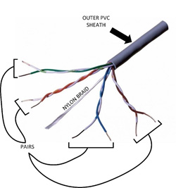
The image above is of a CAT5e U/UTP cable. The nylon braid is non-conductive and is provided as an aid to strip back the outer PVC sheath without damaging the coloured insulation on the conductor cables.
CAT6a U/FTP
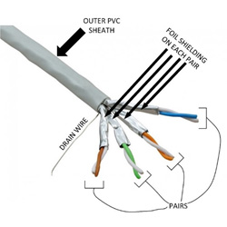
The image above shows a CAT6a U/FTP cable. Each pair has a foil sheath to protect them from the effects of EMI and from crosstalk which may be induced by the signals carried on other pairs. Also present is a drain wire, this is a conductive strip which runs along the entirety of the cable run. The drain should be connected to the shield of the termination points at each end of a cable run providing a ground path for any unwanted signals.
CAT6a S/FTP
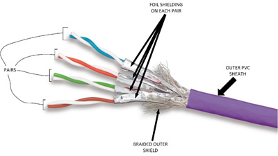
The final example above is of a CAT6a S/FTP cable. The only difference from the previous example is the addition of a braided shield within the outer PVC shield surrounding all four pairs. This provides a further barrier to any EMI. This braided shield should be connected to the shield at the termination points.
With any of the above examples, when it comes to category cable there are two choices, solid core and multi-core (in some cases referred to as stranded core).
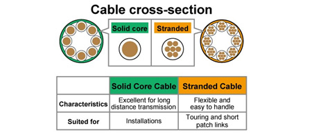
The above images give a visual representation of the make up of the cable and their benefits and restrictions. For any HDBaseT install it is advised, and this is true of any infrastructure cable, the use of solid core cabling for most of the run from patch panel in comms cupboard to network point and then as short as possible stranded core ‘patch’ cables to complete the run at both ends. First reason for this is that termination points within infrastructure tend to be designed for push-down termination.
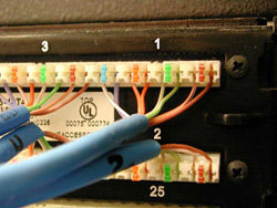
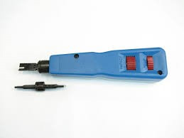
On the top, above is an image of a push down termination patch panel and on the bottom the associated tool required. The solid core cable is pushed in to the correct position and then small blades within the termination point cut through the conductor’s insulation and grip on to the conductor. Secondly solid core cables are far more capable at long distances, stranded cables over long distance can cause degradation in signal quality.
The cable specification below has been rigorously tested by Smart-e engineers and verified to transmit a 3840×2160, HDCP2.2, 4:2:0 specification image over a distance of 100m.
- Connectix CAT6a U/FTP Solid core cable (up to 90m)
- Connectix CAT6a Keystone modules x2
- Connectix CAT6a S/FTP 5m Stranded core patch cables x2
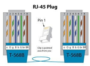
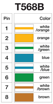
T-568B Termination at both ends
The cable choices listed above have proved to provide near perfect operating conditions for the transmission of HDBaseT signals over long distances. At 100m HDBaseT is at the very limit of performance with the image specification given above, one way to mitigate against this is with the use of a HDBaseT 2.0 specification receiver unit such as the 4K-RX975-USB. HDBaseT 2.0 specification is yet more robust to noise than standard HDBaseT products, at 100m with the specifications set above the same performance levels were observed as were seen at 70m with HDBaseT specification products.
- The cabling used for HDBaseT (CAT5e and above) is the same as that used in LAN applications. For this, many standards have been developed within the industry. In Britain the BS 6701:2016 is the latest version of document available entitled Telecommunications equipment and telecommunications cabling – specification for installation, operation and maintenance. Similar standards exist in other regions around the world. Adhering to the specifications set out in these documents is a key start point for the installation of any category cable project.
- Make sure a distance is kept between power cables and category cabling. A general rule of thumb is these types of cables should be 12 inches apart. It can be tempting, especially in commercial installations, to run power and catx cables in shared trays and trunkings but this can lead to large amounts of EMI induced in to category cabling and ultimately performance issues.
- All category cables should be handled with great care. A common cable tidy solution is the use of cable ties or other similar items, these can crush and break the conductor cores within category cables leading to decreased performance. When pulling cables please use minimal force necessary, if a too larger force is being required return to the beginning of the cable run and try again.
- Use of patch cables should be kept to an absolute minimum. Every join within a system introduces small losses, as outset previously, the majority of a cable run should be a solid core infrastructure category cable and a maximum of 5m stranded patch cable should be used at each end of the run.
- Be careful of bends within cable runs. The inside bend radius of a cable when installed should be at least 4 times the diameter of the cable. This is a rule of thumb and there is tolerance either way but if a cable is bent significantly within this rule it can lead to the cable properties being changed and affecting system performance.
- Keep termination points as small and as neat as possible. Untwisting category cabling reduces the performance of the cable and stripping back the insulation and shielding leaves the conductors vulnerable to EMI, for this reason you should strip back the minimum amount of shielding and sheaving as is possible.
- Take great care with termination process. Use of approved wire stripping and termination tools is vital to ensure the quality and longevity of the connection. Be sure of the termination scheme used at both ends of a cable run and adhere to this termination across all installed cabling, T568B is the widely used termination standard by HDBaseT manufacturers but please check for your specific installation.
- Always monitor cable distances. Most category cabling will have meter markings on the outer sheath, so you can monitor the distance of cabling being installed. It is important to have a note of all cable distances as this can affect the choice of HDBaseT hardware or the operation mode the hardware must be used with.
- Test every cable after termination. Use of a fluke meter or similar test equipment to check all category cabling during install is vital, wrongly wired, damaged or too longer cable can lead to performance issues or damage to hardware.
- Be sure to label all cabling ends and produce a system drawing with all wiring points clearly marked to match the fitted labels. Although a long and what might seem at the time thankless task, when it comes to fault diagnosis labelled cables and a system diagram can save time and money and easily lead to the resolution of a fault that otherwise would be difficult to find.
Tech Support Contact Details
If you are unable to find a solution to a technical issue in our Troubleshooting Guide or Product Manuals, then you can get in contact with our engineering staff by emailing support@smart-e.co.uk.
Alternatively, you can call us on +44 (0) 1306 628264 to speak directly to a member of our engineering team. Simply press 2 for Support when asked to route your call, and we will be happy to assist you.
Smart-e is currently trialling our own maintenance contract service. If you are interested in a Smart-e maintenance contract, then please call us to discuss your particular needs.
Returns and Warranty
Since 1st April 2008 all our products are under a 3 year return to base warranty. In addition to this, an extended (5 year) warranty can be purchased for any product. If a product is purchased and believed to be faulty, it can be sent back for repair or replacement.
To return an item, first please email support@smart-e.co.uk or call +44 (0) 1306 628264 to ask for a Returns Merchandise Authorisation (RMA) number. Once you have your number, then fill out Smart-e’s RMA form and use the given shipping label to return the product along with your completed RMA form.
To view our warranty policies in full, as well as to download our RMA form, please click the link here to be taken to our Compliance Downloads page.